
What is OpenAR?
OpenAR is an open access project hailing from the University of Eastern Finland. The aim of the project is to build cheap, hobbyist friendly augmented reality glasses, and then share everything about them to everyone! Currently there are following iterations:
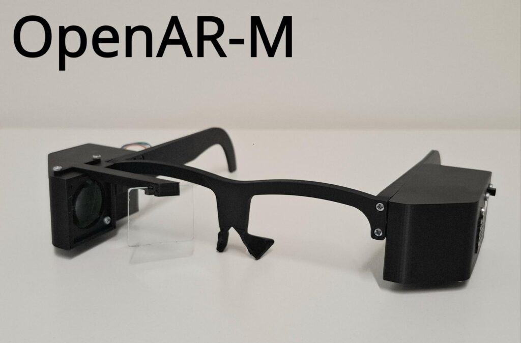
OpenAR-M: The latest, more compact version of the mainline OpenAR glasses.
OpenAR 2.2 Bluetooth: Glasses include an integrated Bluetooth module.
OpenAR 2.1 Thermal: Glasses include a thermal camera.
OpenAR 2.0: Refined version of the first glasses with better modularity. Basis for the 2.1 and 2.2 models.
OpenAR 1.0: The first version.

Who is it for?
Tinkerers, electronic hobbyists, schools, companies interested in AR, augmented reality enthusiasts… the list goes on. Our latest iterations rock the most hobbyist friendly parts imaginable. If you have ever done electronic soldering, then you can be able to build our AR-glasses from start to finish.
How much does it cost?
This is the best part. The price of the OpenAR -glasses can be as low as 30€! The total price varies between 30 – 150€ and this variance is mainly due to the electronic parts.
Where can I find more information about building the OpenAR -glasses?
Right here! Below are links to view the current four iterations of the current OpenAR projects. We recommend focusing on OpenAR 2.0 first, if you are interested in building them yourself. It is the version that kickstarted the version 2 lineup.
Click here for more information about OpenAR-M
Click here for more information about OpenAR 2.2
Click here for more information about OpenAR 2.1