OpenAR 1.0 background information
Light Traveling from an OLED Display to The Eyes
When it comes to optics, not everything is ideal in our system but, it does not really matter since our brain totally ignores most of these imperfections. All we needed to do was get it close enough. For this reason, the device is not meant to be worn for long periods. It would cause a headache. But after all, this was only meant to be a small demonstration of electronics, optics, programing and 3D printing.
So, the image comes from a small OLED display and, in this case, it just shows distances in meters like “1.40 m”. Then, the light goes through a lens, reflects from a mirror, and then again partially reflects off the glass plates into the viewer’s eyes. Sound extremely simple, but some crucial things are happening to the light during this journey.
Collimating Light
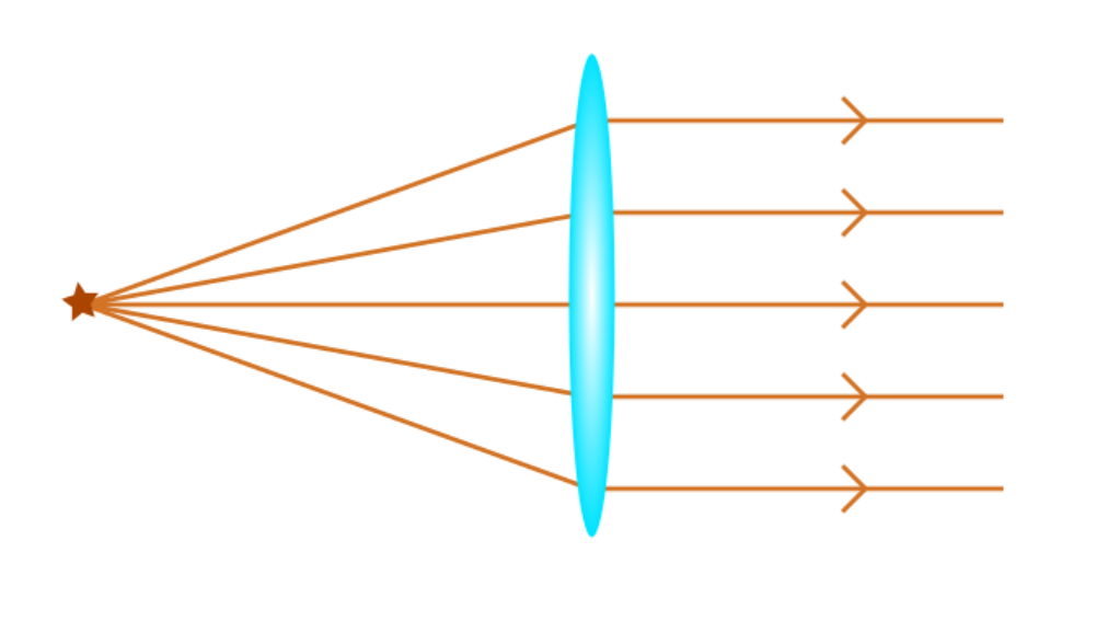
The purpose of the lens is to collimate light that goes through it in order to get the same size image reflecting towards both eyes and to get rid of the double image from the front and rear surfaces of the glass plates. Collimation means that all the light rays are parallel after the lens. With a convex lens (preferably with a plano-convex lens), all the light that comes from the focal point of the lens is collimated.
So, the display should be placed close to the focal point of the lens. It’s best to have a mechanism to adjust this distance a little to find the ideal focus for your eyes.
Focal Length and Lens Diameter
The diameter of the lens affects to your field of vision. If you use a small diameter lens and/or a lens with a short focal length, you’ll only see a small part of the display.
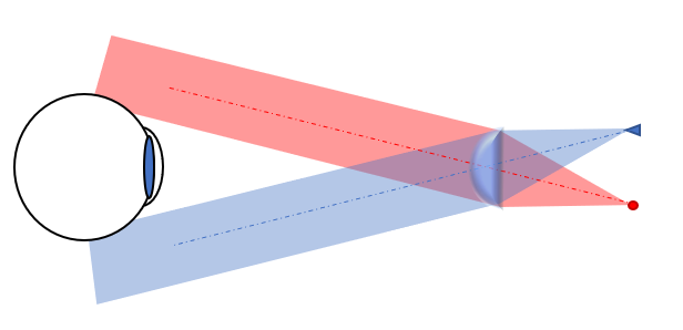
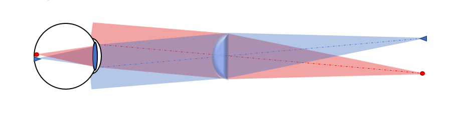
In these pictures, I’m trying to demonstrate light traveling from two points (they could be two pixels at the sides of the display) to one’s eye. With a small diameter lens that has a short focal length, one can’t see the pixels at the sides. Of course, one would still see the pixels in the middle of the display. As a result, if you are planning on using a different kind of lens, remember the focal length and lens diameter will affect the area you can see.
If you want to see how the light beams travel through this system, you can use a ray optics simulators. I like this one.
Light Traveling Through the Glass Plates
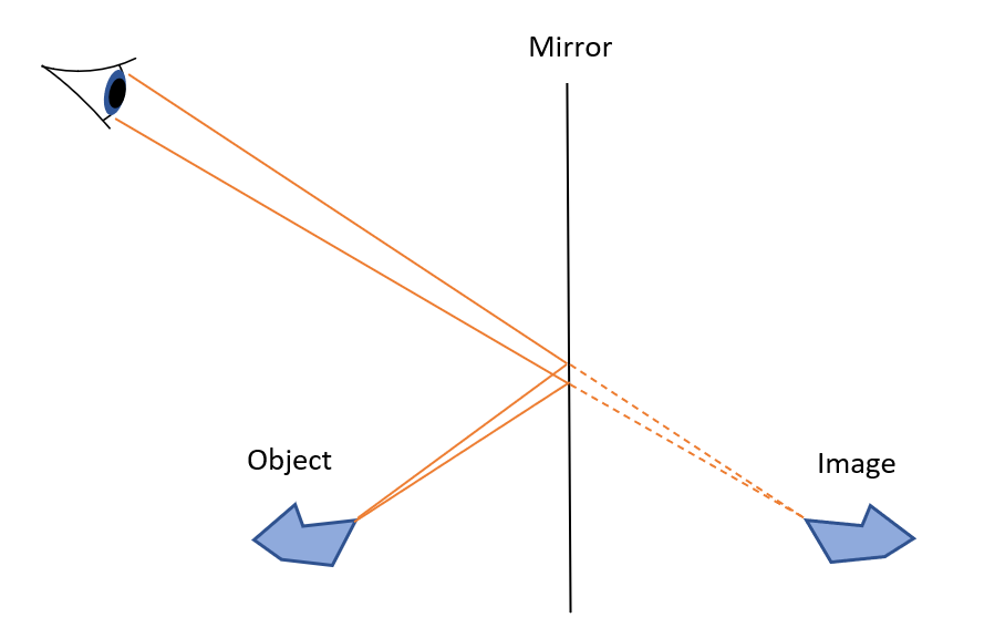
The ray of light approaching the glass surface is called the incident ray. The angle between the glass surface and the line perpendicular (or normal) to the surface of the glass is called the angle of incidence. According to the law of reflection, the angle of incidence is equal to the angle of reflection. In this case, the reflected rays are the ones that are going to hit your eye and eventually make you see the image. The image that you see appears to be in the direction where the light hits your eye. Probably simplest to demonstrate this with a mirror.
Every air-to-glass and glass-to-air interface reflects about 4 % of the light. (To be precise, 4 % reflection happens only assuming perpendicular incidence angle (α=0°) and no absorption or scattering. In this case, the total reflected light from the glass plates is around 15-20 %, depending on the angle of incidence. For this application, we don’t need to know the accurate proportion.)
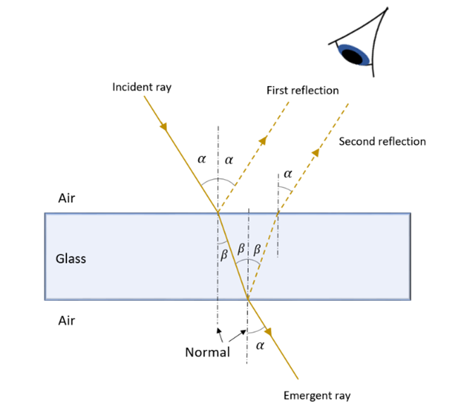
This means that both eyes receive two images, one from the front surface and one from the rear. This double reflection would naturally make you see double or make the image blur. However, by collimating the light, you will see only one sharp image for each eye. The lens in your eye can focus all collimated parallel rays to the same point. So, if you see a double-image with one eye, you need to adjust the distance between the lens and the OLED display.
Most of the light will travel through the glass. In the picture, this pierced part is called an emergent ray. Then the light hits the second glass plate in front of the other eye. Again, similar partial reflection occurs. The light doesn’t travel straight through the glass, but there is a small lateral displacement with the emergent ray compared to the incident ray. Since it’s only about 0.33 mm, with 1 mm thick glass plates, you don’t really need to think about this when building the headset.
First Surface vs. Second Surface Mirrors
This double image problem is the reason why accurate optical devices have first surface mirrors. The first surface mirror has the reflecting layer, usually aluminum, on the top. Then all the light reflects from the first surface of the mirror, creating one accurate image. With a regular (second surface) mirror, the aluminum layer is behind some glass, so some light reflects from the first surface before reflecting from the aluminum. Since the first surface reflects as well, one gets a double image if the light is not collimated. With this application, it doesn’t matter whether you have a first or second surface mirror if you have the lens before the mirror since the light will then be collimated. If you have the mirror before the lens, you will get a double image with a second surface mirror. So, if you want to change the setup, you might want to consider this. The good thing about regular mirrors is that it is much easier to clean them. Glass is easy to wipe clean whereas a single fingerprint can ruin a first surface mirror. If you wipe soft aluminum, all you get is a plate full of scratches.
Combining Separate Images to the Left and Right Eye
Getting rid of the double reflection from a single glass plate does not change the fact that the left and right eye get separate images. Combining these images is something your brain can do if the circumstances are correct, or at least close enough. Practically, this means that you have to adjust the angle of the glass plates. From our brain’s point of view, if the light does not seem to come from the same origin, it lets us see two images. You will just see two reflections from the OLED display floating in the air at some distance. By changing the angle of the reflecting plates, such that the light seems to travel from the same point to both eyes, your brain just decides to combine these images. I believe you will find this is a funny phenomenon when you try it. The images do not need to be that close for them to combine. Suddenly, they will just appear that way.
Human 3D Vision
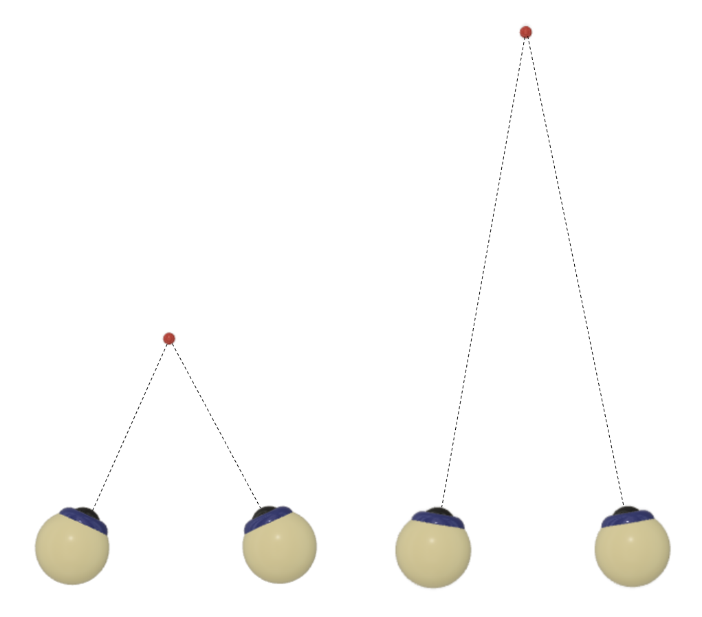
There are plenty of different mechanisms that enable our three-dimensional vision. These are divided into binocular and monocular cues. Binocular cues are based on us having two eyes about 6 – 7 cm apart. Our AR-glasses system is using a binocular cue called binocular vergence for depth perception. Convergence refers to the simultaneous inward movement of both eyes toward each other. If you want to see a precise image, you have to look in the direction where the light comes from. If you look at something in a long-distance, your eyes are almost looking straight forward, and if you look at something close to you, the muscles in your eyes have to work to rotate your eyes inwards. From this muscle work and stretching of the muscles, our brain gets a quite precise idea of the location of the object. Of course, our eyes do a bit more than rotate in their holes. The lens in the eye changes its shape actively to bring images into focus. When you look far away, the lens is slim. When you look close up, the muscles in your eye make the lens thicker. This mechanism will only give us an idea of the distance of the image, though. It does not make us see a 3D image.
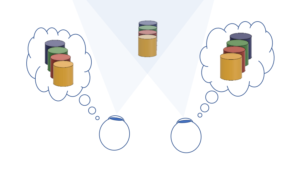
If you want to see a three-dimensional image, you need another type of binocular cue, stereopsis. If you look at some object, your left eye sees it from a slightly different angle than your right eye. That means you will receive two different kinds of images. Yet we “see” only one three-dimensional image, a combination of these two images, which is a product of our brain. To use this in AR-glasses you would need two displays, both showing slightly different images. Then you would have to find a way to bring these images separately to the left and the right eye.
There are also many ways to estimate 3D shapes and distances with one eye only. They are called monocular cues. These can conclude, for example, from the object’s size, shadows, contrast, perspective, etc. If you want to know more, here is one page with more information.
Using Arduino IDE
Attach your Arduino Nano to your computer with a UBS wire. Copy the code you want to use and paste it to the coding window. Define your board by selecting Tools → Board → Arduino Nano. Select the processor Tools → Processor → ATmega328P. Select the port you are using in your computer Tools → Port → you’ll get a list of options. Then click Verify . If you don’t have all the libraries, you will get notification from that library. For example, “Adafruit_SSD1306.h: No such file or directory”. You can add a library selecting Sketch → Include library → Manage library. E.g. write “Adafruit_SSD1306.h” to the search field and install the missing library.
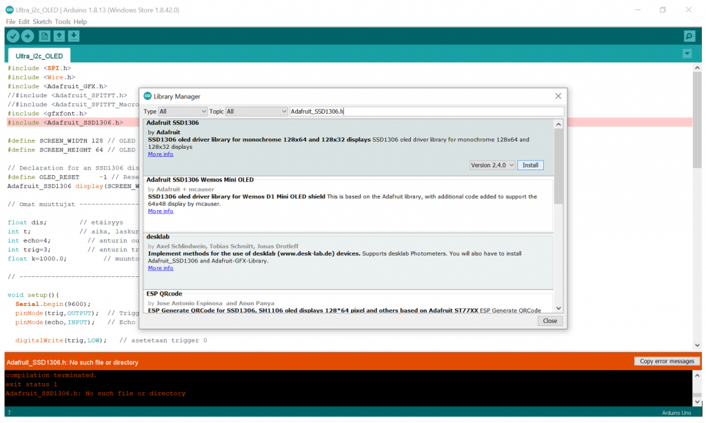
Click Verify again. If no more libraries are missing, you can then send the program to your Arduino by clicking Upload. When the program says “Done uploading,” you are all set.
Cutting Glass or Mirror
Mind the sharp edges when handling glass or mirror plates. Use gloves and goggles. Make a cut across the plate with a glasscutter dipped in oil. You can use a ruler to make a straight line. Snap the glass at the cut by bending the glass plate. Smooth the edges carefully with sandpaper so that you don’t have any sharp edges.
Here is a good video of cutting glass and mirror.