Experimental Combustion Setups
1. Solid biofuel combustion
The solid biofuel combustion facility contains test cells for small scale boilers and batch-wise operated stoves. In addition, the facility consists of a multifuel grate combustion reactor (40 kW) for versatile combustion studies, including aspects from ash behavior, and heat exchanger fouling to formation and characteristics of air emissions. The facility also offers a possibility for test and development work of emission reduction technologies for biomass-fired appliances.
1.1 Small-scale heaters, stoves and boilers
The small-scale combustion research facility is equipped with several log-wood fired stoves and heaters and with a modern pellet boiler (25 kW, Biotech). At the test cell of the batch-fired combustion units the heater is situated on a scale to measure the fuel usage during the combustion and enables balance calculations of the flue gas flow, thermal output and efficiency. The test cell of boilers includes a heat exchanger and sensors to measure heat output and efficiency. In both cases the combustion gases are led through a stack which is equipped with several sampling ports. The draught in the stack can be adjusted by an exhaust fan and changing the location of the hood.
Publications:
Tissari et al., 2015. Zinc nanoparticle formation and physicochemical properties in wood combustion – experiments with Zn-doped pellets in a small-scale. Fuel 143, 404–413.
Tissari et al., 2009 The effects of operating conditions on emissions from masonry heaters and sauna stoves. Biomass and Bioenergy 33, 513–520.
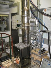
Fig 1. Small scale heater test cell
1.2 Multifuel grate combustion reactor
The grate combustion reactor allows controlled and well-adjustable combustion of various solid fuels, serving as a flexible experimental system for various studies on combustion processes, ash behaviour and emission formation. The system includes a 40 kW solid -fuel burner, a fully logic-controlled fuel feeding system, a ceramic insulated combustion chamber and a firetube boiler with a cooling circuit. The moving reciprocating grate burner is designed for solid biomass e.g. wood chips, pellets, peat and straw, and it is also suited for melt-forming fuels. The setup can be easily modified and different burners, heat exchangers and various emission reduction technologies can be connected to the system, depending on the research needs. The setup includes an option to use oil or gas burner simultaneously with the solid fuel burner. In addition, an electrically heated drop tube furnace can be connected to the system when well-defined temperature conditions are required (e.g. high temperature sampling studies, corrosion studies).
Publications:
Kortelainen, M., Nuutinen, I., Jokiniemi, J., Torvela, T., Lamberg, H., Karhunen, T., Tissari, J., Sippula, O. (2015) Ash behavior and emission formation in a small-scale reciprocating-grate combustion reactor operated with wood chips, reed canary grass and barley straw. Fuel 143, 80-88.
Grigonyte, J., Nuutinen, I., Koponen, T., Lamberg, H., Tissari, J., Jokiniemi, J., Sippula, O. (2014) Evaluation of a Heat Exchanger designed for Efficient Fine Particle Precipitation in Small-Scale Wood Combustion. Energy & Fuels 28, 6058-6065.
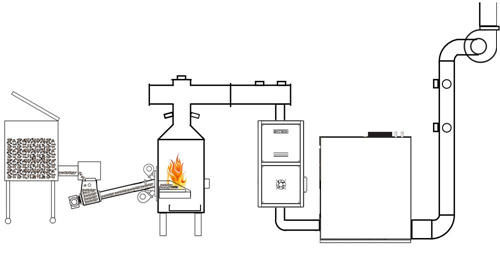
Fig 2. Multifuel grate combustion reactor
2. Vehicle and Engine Emissions
The ILMARI Research Unit is equipped for both engine (Froude consine AG30HS) and chassis type (Rototest VPA-RX3 2WD) dynamometer testing of engines and vehicles.
Technical Data: Rototest VPA-RX3 2WD Froude Consine
Maximum Power 350 kW (469 bhp) 30 kW (40 bhp)
Maximum Torque 2000 Nm 95 Nm
Maximum Speed (hub) 2500 rpm 14000 rpm
Maximum Vehicle Speed 305 km/h (190 mph)
Equivalent wheel
diameter 650 mm
Maximum Axel Load 3500 kg
3. Dilution and Sampling
The laboratory is equipped with several different diluting aerosol sampling systems, including full flow and partial flow sampling systems.
3.1 Porous tube – ejector diluting sampling
The combination of a porous tube diluter with ejector diluters offers a compact partial flow sampling system for emission studies. The system is well adjustable for different sampling conditions. The advantage of the self-developed porous tube diluter units are the negligible losses of fine particles and semivolatile vapours when sampling is carried out from high temperatures. Special versions of the porous tube diluters developed for high temperatures, allow reliable sampling from harsh conditions, such as in-furnace sampling of aerosols. The porous tube – ejector sampling systems are developed further and commercialized by the UEF spin-off company Venacontra (www.venacontra.fi).
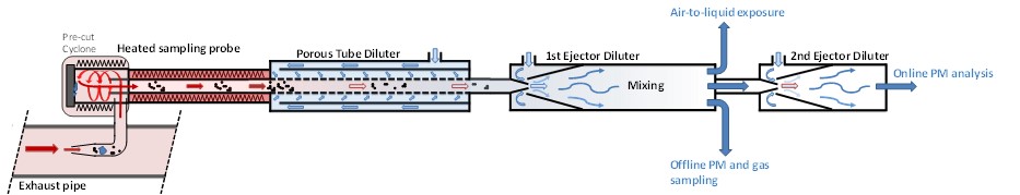
Fig 3. Compact and fully adjustable diluting sampling setup for combustion exhaust measurements, based on the combination of porous tube diluter and ejector diluter
3.2 Dilution tunnel
The stainless steel dilution tunnel offers a possibility for either full flow or partial flow dilution of exhaust gases. The setup is designed according to ISO 8178-1 standard. The tunnel has an inner diameter of 30 cm and the dilution ratio is adjusted by setting the under pressure and flow rate in the tunnel.
Publications:
Sippula, O., Koponen, T., Jokiniemi, J. (2012) Behavior of Alkali Metal Aerosol in a High-Temperature Porous Tube Sampling Probe. Aerosol Science & Technology 46, 1151-1162.
Ruusunen, J., Tapanainen, M., Sippula, O., Jalava, P.I., Lamberg, H., Nuutinen, K., Tissari, J., Ihalainen, M., Kuuspalo, K., Mäki-Paakkanen, J., Hakulinen, P., Pennanen A., Salonen, R.O., Hillamo, R., Hirvonen, M.-R., Jokiniemi, J. (2011) Novel particle sampling system for physico-chemical and toxicological characterization of emissions. Analytical and Bioanalytical Chemistry 401, 3183-3195.
For more information on combustion setups, please contact Prof. Olli Sippula, olli.sippula(at)uef.fi.