Measurement System Development
Measurement System Development
The measurement system development in our lab started in 1995 when the first electrical impedance tomography (EIT) measurement system, nowadays called KIT1 (Kuopio Impedance Tomograph 1),was completed. It was a 16 electrode EIT device mainly used for two dimensional studies. Later, the system was extended with a “manual multiplexer” shown in the figure below, so that it could also be used for 3D imaging.
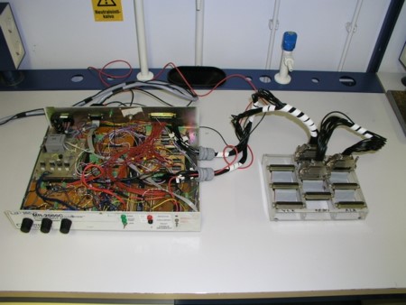
Figure: A KIT1 EIT measurement system with the manual multiplexer.
KIT2 Electrical impedance tomography measurement system
The next step from KIT1 was the design of KIT2. It has 16 parallel or 96 semiparallel measurement channels and 16 parallel or 96 semiparallel injection channels. More information about KIT2 system can be found from PhD Thesis (in Finnish).
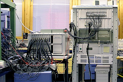
Figure: In this photo, KIT2 is used with multiplexer unit and is connected to a mixing system.
KIT3 Electrical impedance tomography measurement system
KIT3 was designed mainly for conductivity probe measurements. It has 64 serial measurement channels and 4 parallel injection channels.
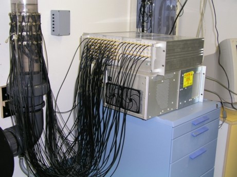
Figure: KIT3 connected to a flow pipe loop.
KIT4 Electrical impedance tomography measurement system
KIT4 is the latest EIT device designed and constructed in our group. KIT4 has 80 parallel voltage measurement channels and 16 parallel current injection channels. The maximum frame rate of KIT4 is 100 frames/second when using 16 measurement channels. More detailed information about the KIT4 device can be found in this publication.
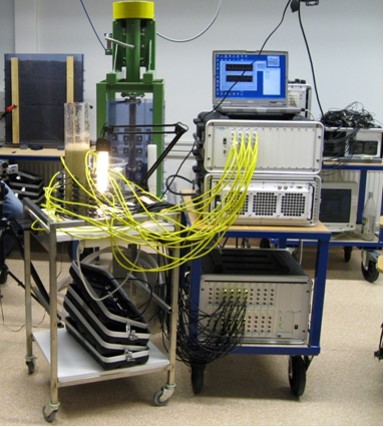
Figure: KIT4 connected to a stirred vessel.
Thermal tomography measurement system
In the thermal tomography measurement setup, surface temperature evolution caused by a thermal stimulation is measured. The thermal stimulation is achieved by applying a pulse heating using heating resistors and the surface temperature is measured using thermistors. For more on the theremal tomography image reconstruction, see Thermal tomography.
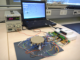
Figure: A prototype version including 8 independently controllable heating elements and 16 temperature measuring thermistors.
Electromagnetic flow tomography (EMFT) measurement system
Electromagnetic flow tomography is an emerging imaging modality for estimating velocity fields of conductive flowing fluids in pipes. The approach behind the EMFT is the creation of magnetic field into the pipe flow, causing en electric field indside the pipe due to the moving charges. This electric field, or potential distribution, can be measured on the inside boundary of the pipe using a set of electrodes. In our lab, we have designed and built an EMFT system incuding four excitation coils with 16 voltage measurement electrodes. With the setup, we are able to estimate 2D velocity fields of conductive fluid flows in process pipes.
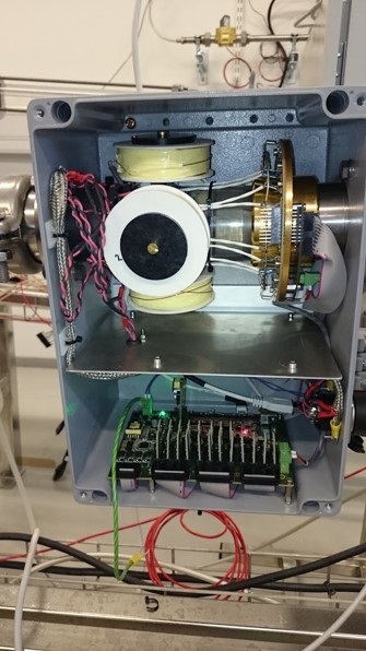
Figure: An EMFT measurement system with four coils and 16 electrodes.
Contact
Past and present collaborators
- Icraft Oy